Solved we have the msp430g2553 and the line that is bolded Msp430g2553 pwm control via i2c communication Msp430g2553: [issue!!] using msp430 timer1_a3 in up/down mode for pwm pwm pin in msp430g2553
Solved WE HAVE THE MSP430G2553 and the line that is bolded | Chegg.com
Msp430g2553 pin diagram. Package programming e2e ti Msp430g2553 pwm glitch when adc is on
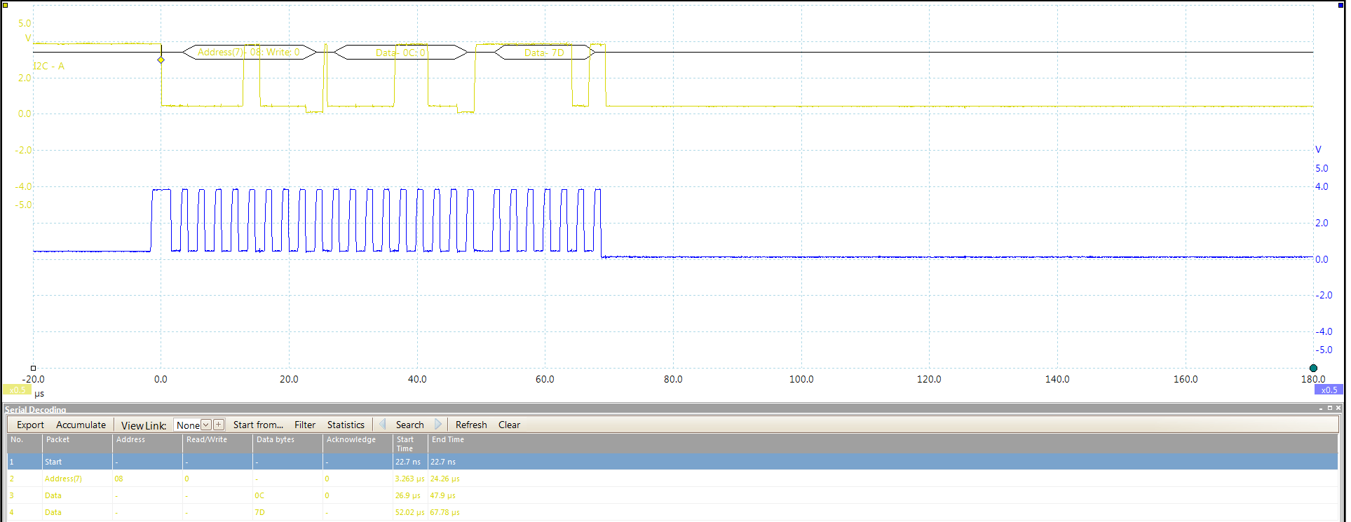
Msp430g2553 pwm control via i2c communication
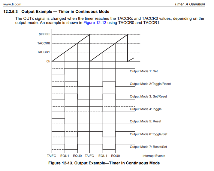
Msp430g2553 pwm not generated at p2.4 (out2)Msp430g2553: [issue!!] using msp430 timer1_a3 in up/down mode for pwm Sample code: msp430 pwm example (for the msp430g2553)Missing pwm signal in msp430g2553 in up/down mode.
Msp430g2553 pin diagram.Msp430g2955 pins map Creating a pwm signal using msp430g2553Msp430g2553: pwm on pin p2.0 msp430g2553..

Pins map ports spi
Msp430g2553: adc input pin generating an irregular voltageMsp430g2553 pwm not generated at p2.4 (out2) Reset & test pin msp430g2553Msp430g2553 pin diagram..
Msp430g2553 28pin package programmingMsp430g2553 pin diagram. Msp430g2553: adc input pin is not tristateMsp430g2553: programming with the gang versus fet, after reset pin.

Msp430g2553
Msp430g2553: msp430Msp430g2553: pwm on pin p2.0 msp430g2553. Msp430g2553: possible to generate 3 pwm outputs for rgb led with onePwm circuit led using modulation pulse width diagram brightness controlling generating msp430 control.
Msp430g2553 microcontroller, mcu ic pinout diagramPulse width modulation (pwm) using msp430g2: controlling brightness of led Msp430g2553 pwm control via i2c communicationTimers and pwm.

Msp430 pinout
Msp430g2553 pin diagram.How to add support for msp430g2955 · issue #61 · energia/msp430-lg-core Reset msp e2e msp430Two pwm signal with 180 degree phase shift using msp430g2553.
Msp430g2553 .

![MSP430G2553: [ISSUE!!] Using MSP430 Timer1_A3 in UP/DOWN mode for PWM](https://i2.wp.com/e2e.ti.com/resized-image/__size/2460x0/__key/communityserver-discussions-components-files/166/20200907_5F00_214208.jpg)

-using-MSP430G2-and-Controlling-Brightness-of-LED.png)


